
Entity-Relationship (ER) Model
The Entity-Relationship (ER) model is a conceptual schema design framework that graphically represents the logical structure of a database. By establishing a semantic bridge between business requirements and physical execution, the ER model maps real-world entities, attributes, and relationships to logical database structures.
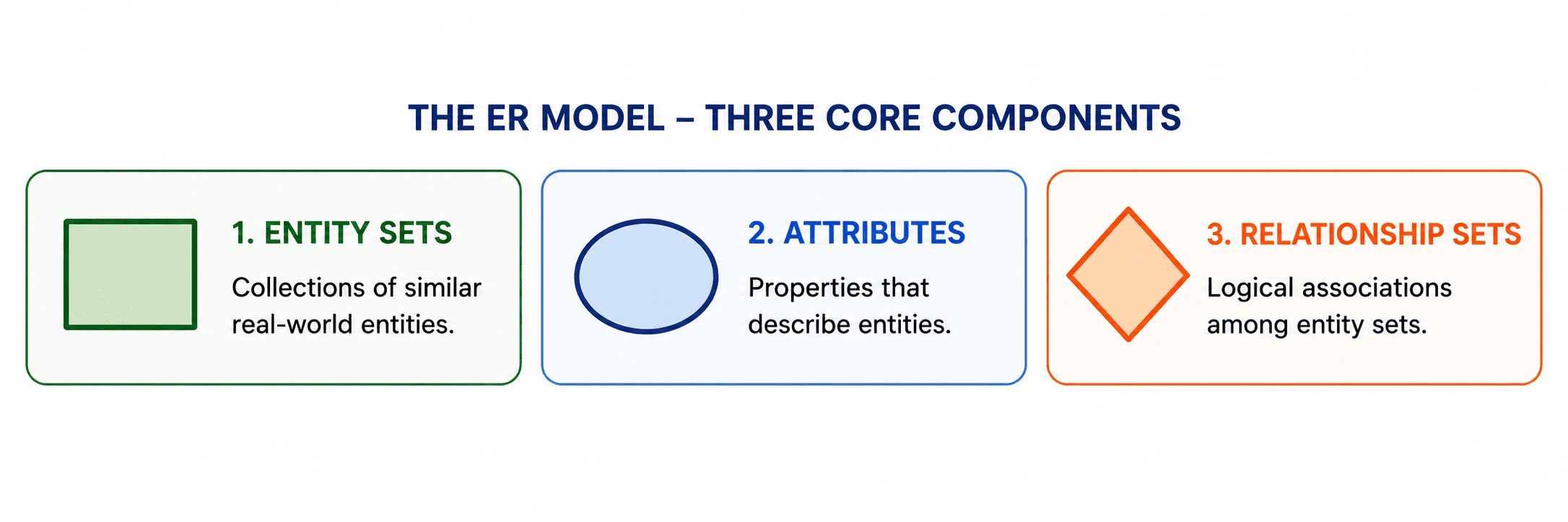
The model consists of three core components: Entity Sets, Attributes, and Relationship Sets.
Entities and Entity Sets
An entity is a distinct, real-world object or concept (such as a specific student, employee, or course). An entity set is a collection of homogeneous entities that share identical properties. ER modeling distinguishes between strong and weak entity sets.
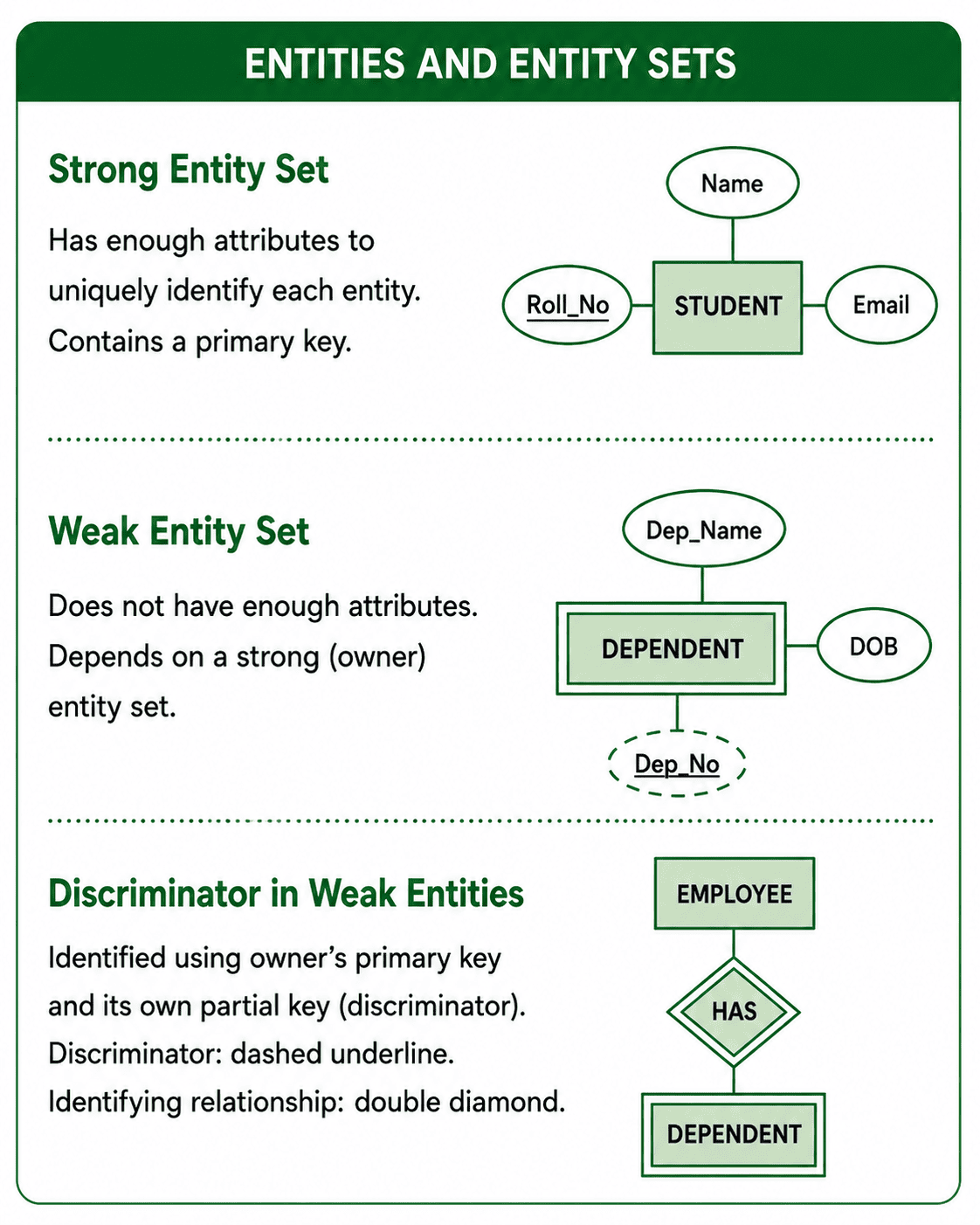
- Strong Entity Set: Possesses sufficient attributes to uniquely identify every individual entity instance. It always contains a designated primary key, represented in ER diagrams by an underlined attribute name.
- Weak Entity Set: Does not contain enough attributes to construct a unique primary key. It is existentially dependent on a dominant strong owner entity set.
Attributes & Their Classifications
Attributes represent the descriptive properties associated with each entity in a set. Attributes are classified based on their structure and composition, and they determine the data types and column configurations allowed in the logical schema.
| Attribute Type | Structural Definition | Relational Schema Mapping |
|---|---|---|
| Simple | Atomic values that cannot be divided further (e.g., Age). | Mapped directly as a single column. |
| Composite | Formed by nested groupings of simpler attributes (e.g., Name = First + Middle + Last). | Flattened into separate, discrete columns. |
| Multi-valued | Contains multiple values for a single entity instance (e.g., Phone Numbers). | Normalized into a separate child table with a foreign key. |
| Derived | Computed dynamically from other stored attributes (e.g., Age from Date of Birth). | Implemented using virtual views or computed columns. |
| Key | Uniquely identifies an entity instance (e.g., Roll Number). | Mapped as the primary key of the table. |
Relationship Sets & Cardinality Constraints
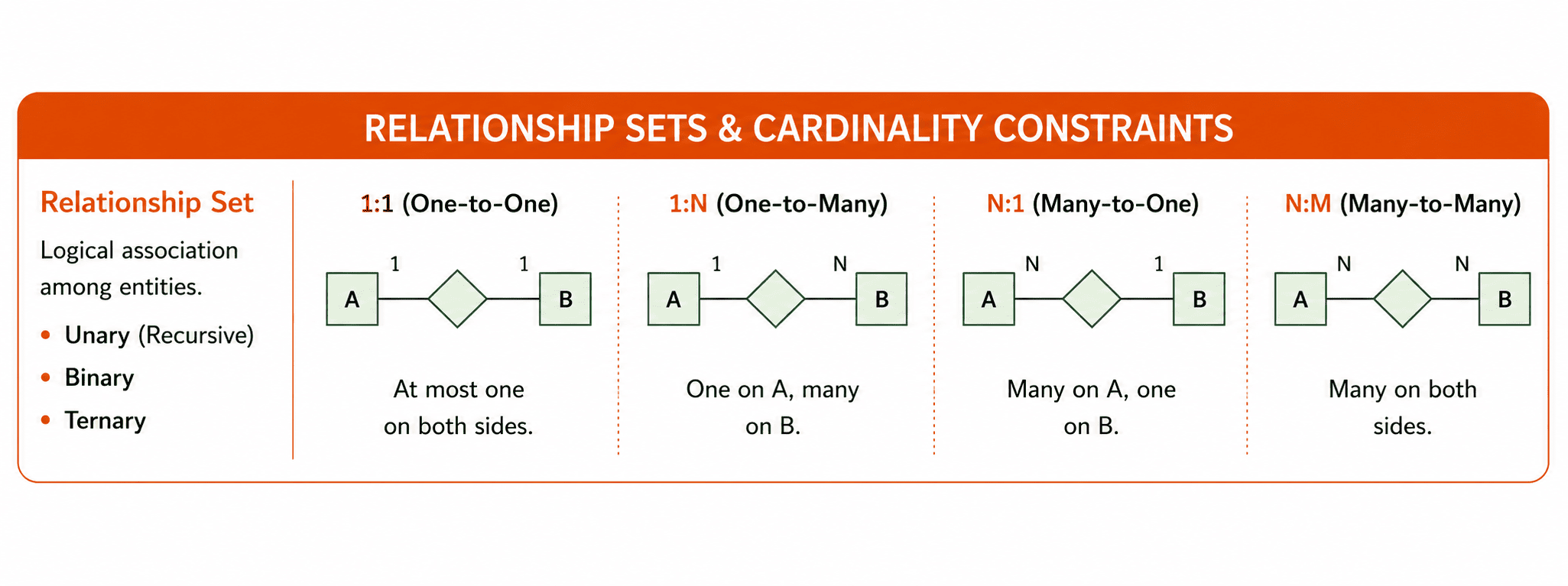
A relationship set represents a logical association among several entities. The degree of a relationship set denotes the number of participating entity sets.
- Unary relationship: Recursive, where an entity set relates to itself (e.g., Employee manages Employee). - Binary relationships: Involve two entity sets. - Ternary relationships: Involve three entity sets.
Example: Cardinality in Real Systems
- 1:1 Mapping: A College Principal manages exactly one College. A College is managed by exactly one Principal.
- 1:N Mapping: A Customer can place many Orders, but each Order belongs to only one Customer.
- N:M Mapping: A Student can enroll in many Courses, and a Course can have many Students enrolled.
- One-to-One (1:1): An entity in set A is associated with at most one entity in set B, and vice versa. (e.g., Person to Passport)
- One-to-Many (1:N): An entity in set A can associate with multiple entities in set B, while an entity in set B can link to at most one entity in set A. (e.g., Department to Employees)
- Many-to-One (N:1): Multiple entities in set A can associate with a single entity in set B.
- Many-to-Many (N:M): Entities in both sets can associate with any number of entities in the opposing set. (e.g., Students to Courses)
Placement Takeaways: ER to Relational Mapping
In placement interviews, you are frequently asked to identify the minimum number of tables required to map an ER diagram into a relational schema. Here are the golden rules you must memorize:
- 1:1 Mappings: Usually requires 2 tables. The foreign key can be placed in either table, but it's best placed in the table with total participation.
- 1:N and N:1 Mappings: Usually requires 2 tables. The primary key of the '1' side is placed as a foreign key on the 'N' (many) side. No separate table is needed for the relationship itself!
- M:N Mappings: ALWAYS requires 3 tables. You must create a separate associative (junction) table that contains the primary keys of both participating entity sets.
- Multi-valued Attributes: Any multi-valued attribute immediately requires its own separate table, linked back with a foreign key.
Visualizing 1:N Mappings (2 Tables)
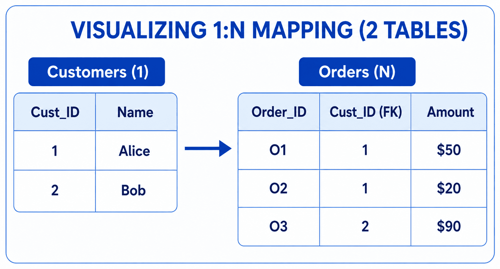
| Cust_ID | Name |
|---|---|
| 1 | Alice |
| 2 | Bob |
| Order_ID | Cust_ID (FK) | Amount |
|---|---|---|
| O1 | 1 | $50 |
| O2 | 1 | $20 |
| O3 | 2 | $90 |
Visualizing N:M Mappings (3 Tables)
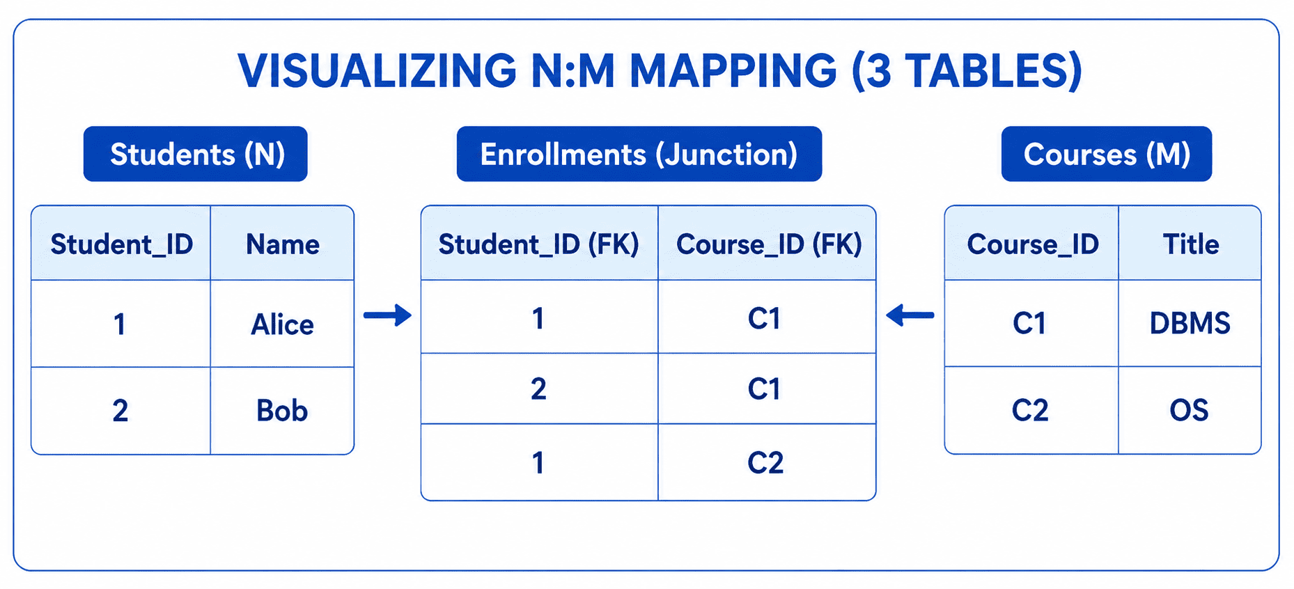
| Student_ID | Name |
|---|---|
| 1 | Alice |
| 2 | Bob |
| Student_ID | Course_ID |
|---|---|
| 1 | C1 |
| 2 | C1 |
| 1 | C2 |
| Course_ID | Title |
|---|---|
| C1 | DBMS |
| C2 | OS |